
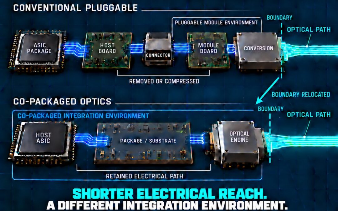
CPO MOVES THE BOUNDARY
From the faceplate to the package—and into a different integration environment.
Co-packaged optics is often described as moving optics closer to silicon.
That is correct, but it does not capture the full architectural change.
The deeper consequence is that the boundary between electrical and optical transport moves from one system environment to another.
That relocation can substantially shorten the electrical reach. It can also change which electrical, optical, thermal, mechanical, manufacturing and service conditions must be managed together.
The distance changes.
The surrounding architecture changes with it.
From the faceplate to the package
In a conventional pluggable architecture, the high-speed electrical signal typically travels from the host ASIC through the ASIC package, across the host board, through an electrical connector and onto the module board.
Electro-optical conversion occurs inside a module near the system faceplate.
This arrangement creates a comparatively long electrical route with multiple interfaces. It also establishes a clear physical and service boundary between the host system and the optical module.
CPO changes that arrangement.
By positioning the optical engine beside the host ASIC within a co-packaged assembly, substantial host-board routing can be removed or compressed. The conventional electrical connector and portions of the module-board path may also be eliminated.
The OIF Co-Packaging Framework Document describes an illustrative CPO operating point that includes approximately 50 mm of first-level packaging substrate and approximately 10 dB of loss at Nyquist, including package parasitics from the host ASIC and optical-engine assembly.
That operating point is not a universal definition of every CPO implementation. It demonstrates something more fundamental:
A finite electrical channel remains between the host ASIC and the optical engine.
CPO shortens that channel and relocates its endpoint.
What the new location can improve
Shortening the electrical reach can create meaningful architectural benefits.
It can reduce insertion loss, remove conventional impedance discontinuities and reduce the electrical burden placed on the signal before conversion. Depending on the implementation, that can support higher bandwidth density, lower signal-conditioning requirements or improved power efficiency.
These are important reasons for moving optics closer to the host ASIC.
The point is not to question the value of shorter electrical transport.
The point is to understand the complete architecture that shorter transport creates.
What moves with the boundary
The electro-optical boundary does not move in isolation.
When the optical engine moves from a faceplate module into a co-packaged environment, several system relationships change with it.
Package routing and electrical reference structures must operate within the physical constraints of the integrated assembly.
Power delivery for the host ASIC, electronic circuitry and optical engine must be coordinated within a more concentrated environment.
Thermal paths must account for the proximity of high-power digital silicon and temperature-sensitive optical components.
Optical attachment, alignment and laser architecture become part of the package and system integration strategy.
Assembly sequence, test access and manufacturing yield must be considered across components that may previously have been built and qualified as separate units.
Serviceability also changes when optical functions that once resided in a replaceable faceplate module become more closely associated with the host package.
None of these conditions makes CPO inherently better or worse.
They are architecture-dependent variables. Their significance depends on the particular package, optical engine, interface architecture, cooling strategy, manufacturing process and service model being evaluated.
Integration concentrates relationships.
It does not predetermine their outcome.
The conversion remains, but its context changes
Moving the optical engine does not remove the fundamental handoff between electrical and optical transport.
On the transmit side, electrical activity still drives the circuitry and photonic structures that produce the optical signal.
On the receive side, optical energy must still be detected and converted into an electrical response for the host system.
Different implementations can distribute drivers, amplifiers, retiming, laser functions and control circuitry differently. CPO therefore does not describe one universal internal architecture.
What these implementations share is a relocation of the transport boundary.
The electrical path ends closer to the host ASIC.
The optical path begins earlier in the system.
The surrounding electrical, optical and package relationships become more tightly coupled.
Boundary placement is a system decision
The location of conversion helps determine more than channel length.
It helps determine where power is consumed, where heat must travel, where optical attachment occurs, how the assembly is tested and what can be replaced or serviced independently.
That makes boundary placement a system-level architectural decision.
A complete evaluation should ask:
- Where does electrical transport end, and where does optical transport begin?
- Which electrical regions and interfaces are removed, retained or created?
- What measurable channel or system advantage does the new location produce?
- Which package, power, thermal, optical and manufacturing conditions must be controlled to preserve that advantage?
- How will the integrated path be assembled, tested, qualified and serviced?
- Do the measured benefits remain material after those dependencies are included?
These questions do not argue against CPO.
They provide a more rigorous way to evaluate it.
The system must retain the advantage
Moving the boundary is valuable when the complete system preserves the benefit that motivated the move.
A shorter electrical path may reduce channel loss and conventional discontinuities. Whether that improvement translates into the desired system-level result depends on the architecture surrounding the path.
The correct comparison is therefore not simply copper versus optics.
It is not merely pluggable versus co-packaged.
It is the measured performance, power, density, thermal behavior, manufacturability, testability, serviceability and lifecycle value of the complete system created by each boundary location.
CPO moves the boundary.
The architecture must preserve the advantage across it.
At Mitas Electronics, we are examining where electrical and optical physics naturally belong as computing architectures scale—and what high-speed systems must preserve as transport moves across the boundaries between them.
The architecture comes before the technology.
And the boundary is part of the architecture.