
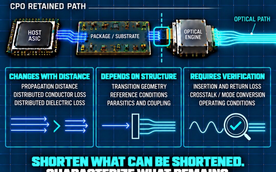
Why CPO reduces electrical distance without reducing the channel to a single metric
Co-packaged optics creates real architectural value by moving the optical engine closer to the host ASIC.
The resulting electrical path can be substantially shorter than the route used with conventional faceplate-pluggable optics. Within an otherwise comparable passive channel, reducing that distance can decrease propagation delay and the conductor and dielectric losses accumulated along the route.
Those benefits matter.
But they do not mean every channel impairment decreases in proportion to length—or that insertion loss alone can characterize what remains.
A shorter electrical path is still a physical structure. Its behavior depends on how the host ASIC, package or substrate and optical-engine assembly are connected, referenced, manufactured and operated.
The path becomes shorter.
The obligation to understand it does not.
What changes with distance?
Some channel effects are distributed along the transmission path.
Conductor loss accumulates as current travels through conductive material. Dielectric loss accumulates as electromagnetic energy propagates through the surrounding dielectric. Propagation delay also follows physical distance and the properties of the transmission medium.
Within an otherwise comparable channel, reducing electrical reach can reduce these distance-dependent burdens.
This is one of CPO’s clearest potential advantages. Moving optical conversion closer to the host ASIC can relieve part of the electrical-channel burden before the signal enters the optical domain.
But “shorter” describes distance.
It does not completely describe the retained channel.
What depends on structure?
Not every impairment is distributed uniformly along the route.
The retained path includes transitions among the host ASIC, package or substrate and optical-engine assembly. Each transition has physical geometry, reference conditions, parasitics and relationships with surrounding structures.
Its behavior can be affected by:
- Impedance continuity
- Return-current continuity
- Conductor and reference-plane geometry
- Package and attachment parasitics
- Differential symmetry
- Coupling to adjacent structures
- Manufacturing variation
- Frequency and operating conditions
These factors do not necessarily scale with total channel length in the same way as distributed attenuation.
Reducing the trace length adjacent to a transition does not automatically change the physical construction of that transition. Nor does a lower aggregate insertion-loss number, by itself, determine how much reflection, coupling or mode conversion may occur there.
That distinction is central:
Distance shapes distributed loss.
Structure shapes transitions.
Why lower insertion loss is not a complete answer
Insertion loss describes how much signal transmission is reduced through the channel.
Return loss addresses a different relationship: the reflections associated with impedance mismatch along the signal path.
A channel can exhibit lower distributed attenuation while still requiring careful characterization of its retained discontinuities.
The OIF Next Generation CEI-224G Framework draws attention to this distinction. Based on industry experience with low-loss channels, the framework notes the impact that return loss could have and states that 224 Gbps applications and channel metrics will need to give greater weight to factors beyond insertion loss.
The document also illustrates that changing the system reference impedance can produce materially different simulated channel behavior.
These observations should not be interpreted as proof that return loss dominates every CPO implementation. The framework identifies technical considerations for future interface development; it is not a universal performance result or a final specification for every architecture.
Its implication is narrower—and important:
A lower-loss electrical route cannot be considered fully characterized simply because its insertion-loss budget has improved.
Measurement must follow the retained path
CPO changes where electrical-to-optical conversion occurs. That relocation changes which structures remain in the electrical channel and where meaningful reference planes and test points may need to be established.
The OIF Co-Packaging Framework Document notes that achievable distance for several host-ASIC-to-engine interface examples depends on channel impairments including insertion loss, crosstalk, package parasitics and impedance discontinuities. It also anticipates that future implementation agreements would define applicable test points, methodologies and criteria.
That creates a practical engineering requirement.
The retained channel should be evaluated using the measurements appropriate to its specific implementation. Depending on the interface and architecture, that assessment may include:
- Insertion loss
- Return loss
- Crosstalk
- Differential-to-common-mode conversion
- Time-domain impedance behavior
- Reference-plane and de-embedding discipline
- Performance across relevant manufacturing and operating conditions
No single list applies identically to every implementation. The measurement plan must follow the actual package, electrical interface, optical-engine attachment and intended operating environment.
The objective is not to add measurement for its own sake.
It is to ensure that the claimed benefit of shortening the channel remains measurable after the retained structure is included.
The broader CPO decision remains systemic
Electrical-channel analysis is only one layer of the CPO problem.
Moving optical conversion into or near the package also changes thermal management, laser and optical integration, power delivery, assembly, test access, manufacturing yield, rework, serviceability and lifecycle economics.
Improved electrical reach does not automatically resolve those dependencies.
Nor do those dependencies negate the value of a shorter electrical path.
They establish why CPO must be evaluated as a complete system rather than as an isolated optical or electrical substitution.
The relevant question is not simply:
How much distance was removed?
It is:
What remains in the path, how does it behave, and can the complete implementation be manufactured, tested and operated with sufficient control?
A disciplined decision principle
CPO should receive full credit for the electrical distance it can remove.
But the retained path should not receive less scrutiny because it is shorter.
A disciplined assessment should:
- Quantify the distance-dependent burdens that decrease.
- Identify the physical transitions and reference conditions that remain.
- Define measurement planes and methods appropriate to the implementation.
- Evaluate relevant variation and operating conditions.
- Integrate the electrical findings with thermal, optical, reliability, manufacturing and economic evidence.
The principle is straightforward:
Shorten what can be shortened.
Characterize what remains.
Judge the architecture by whether its measured system-level benefit remains material after the complete implementation is considered.
Mitas Electronics
Engineering the future of high-speed data transport.
CPO MOVES THE BOUNDARY
What must the system preserve across it?
References
OIF-Co-Packaging-FD-01.0, Co-Packaging Framework Document
OIF-FD-CEI-224G-01.0, Next Generation CEI-224G Framework