In today’s world of high-speed, compact electronics, every millimeter counts. Engineers and designers are constantly looking for ways to transmit signals faster, with less loss, and in tighter spaces. Enter the coaxial cable a micro-scale powerhouse that delivers exceptional high-frequency performance without compromising on durability or precision.
From next-gen medical devices to aerospace systems and wearable technology, 40 AWG coax cables are enabling designs that were once impossible. In this guide, we’ll break down the electrical, mechanical, and material science behind these ultra-fine cables, share key design tips, and explore real-world applications where they shine.
1. Electrical and Signal Properties
Signal Integrity
Signal integrity (S-parameters) challenges become amplified at high frequencies and smaller geometries. In small gauge coaxial cables (e.g. 40 AWG.)
- Attenuation increases due to smaller conductor cross-section and higher resistance.
- Crosstalk is well-controlled thanks to the coaxial structure, but spacing between cables in bundles still matters.
- Reflection & Return Loss: Precision impedance matching is essential to avoid signal reflections, which are more pronounced at GHz frequencies.
Typical return loss: >20 dB up to 6 GHz in high-quality assemblies.
Impedance Control
Micro coaxial cables are designed with tight impedance tolerances:
- Typical Single ended impedance: 42.5Ω(PCIe),45Ω(USB-C) and 50Ω (Video).
- Controlled through dielectric thickness, dielectric constant, and conductor spacing.
- ±5% tolerance achievable with precision extrusion and QA control.
Capacitance and Inductance
- Capacitance: ~98 – 164 pF/m depending on dielectric material.
- Inductance: <66 nH/m.
- These influence high-speed signal rise times, noise margin, and EMI susceptibility.
Propagation Delay and Velocity Factor
- Velocity Factor: ~0.66–0.85, depending on dielectric (e.g., PTFE = 0.70).
- Propagation Delay: ~3.9 to 4.9 nanoseconds per meter (ns/m).
- Important for timing-sensitive applications and high-speed digital buses.
High-Frequency Performance
- Skin Effect: At >1 GHz, current concentrates on the conductor surface.
- For 40 AWG wire (~ 0.0799 mm diameter), nearly the entire conductor cross-section lies within the skin depth at 1–10 GHz.
- Signal loss increases with frequency: Dielectric loss and conductor surface finish become critical.
Power Handling Limitations
- Current Rating: ~ 0.5–0.75 A maximum continuous current, depending on insulation and ambient temperature.
- Thermal Rise: Must be managed carefully, especially in tight bundles or enclosures.
- Derating required above 60°C ambient.
2. Physical and Mechanical Characteristics
Gauge-Specific Considerations
- 40 AWG (TYP. 44-32 AWG) conductors are fragile and require careful handling.
- Termination and soldering demand precision tooling and magnification.
- Stranded variants may offer improved durability during flexing.
Flexibility and Bend Radius
- Minimum bend radius: ~5–10× cable diameter.
- Ideal for dynamic applications like robotic joints, medical probes, or wearables.
- Teflon-jacketed versions maintain flexibility at low temperatures.
Weight and Space Savings
- Excellent for high-density assemblies in UAVs, satellites, and surgical devices.
- Typical wire gauges less than 36 AWG coax weigh <2 g/m.
- Space savings enable tighter routing on flex PCBs and in miniaturized enclosures.
Thermal Performance
- Operating Temperature: -65°C to +105°C (PTFE-based versions).
- Excellent thermal stability for aerospace and medical sterilization environments.
- Flame Retardance: FEP, PTFE, and LSZH jackets meet UL94 V-0, VW-1, and applicable aerospace flammability standards.

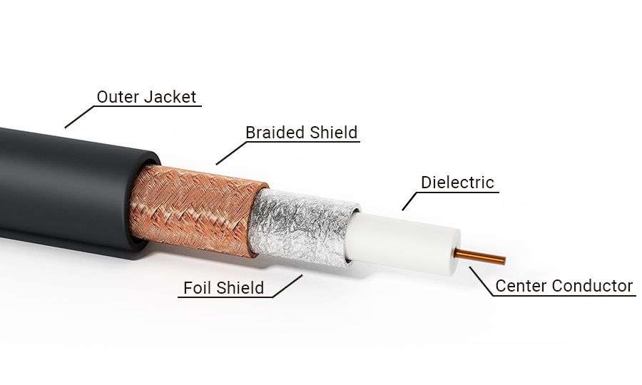
3. Material Composition: Layer-by-Layer Breakdown
Inner Conductor
- Types:
- Solid silver-plated copper (SPC): Lowest resistance, excellent high frequency (HF) performance and corrosion resistance.
- Stranded tinned copper (TC): Good solderability; cost-effective; good mechanical flexibility
- Trade-offs: Silver offers superior conductivity and high-frequency performance; tin provides better solderability and lower cost.
Dielectric Insulation
- Common Materials
- PTFE (Teflon): Stable, low-loss, high-temp.
- FEP: Similar to PTFE but more processable.
- PE or foam PE: Lower-cost, moderate performance.
- PFA:
- Keeps PTFE’s high-temperature limit (~260 °C continuous).
- Maintains PTFE’s chemical inertness.
- Gains FEP’s melt-processability, so you can use conventional thermoplastic extrusion/molding instead of complex sintering.
- Offers better mechanical toughness than FEP, especially at high temps.
- The only real downside is cost. PFA is usually more expensive than either PTFE or FEP.
- Dielectric Constant (εr)
- PTFE ≈ 2.1 (1.35-3.2), PE ≈ 2.3-2.5.
- FEP ≈ 2.1–2.5=2.2, PFA ≈ 2.1 – 2.2,
- Loss Tangent: As low as 0.0002 for PTFE at 1 GHz.
|
Material |
Custom version Dk (Dielectric Constant) |
Notes |
|
PTFE (Polytetrafluoroethylene) |
~1.43 – 1.45 |
Widely regarded as the gold standard for ultra-low Dk and loss; custom formulations may push closer to 1.43 |
|
PFA (Perfluoroalkoxy alkane) |
~1.52 – 1.54 |
Slightly higher Dk than PTFE but excellent chemical resistance and thermal stability; ultra-low loss grades can achieve ~1.52 |
|
FEP (Fluorinated ethylene propylene) |
~1.33 – 1.35 |
Often reported as having the lowest Dk among fluoropolymers; however, slightly higher loss tangent than PTFE in some cases |
Additional Notes:
- Dk values vary based on frequency and specific formulation.
- Ultra-low-loss custom versions often include fillers or processing tweaks to minimize dielectric constant and loss tangent (Dissipation Factor).
- Manufacturers sometimes provide proprietary data; reaching out to them is best for exact custom specs.
Shielding
- Types:
- Foil (100% coverage): Excellent for high-frequency EMI shielding.
- Braid (70–95% coverage): Provides lower DC resistance and greater flexibility.
- Combination Shielding: Foil plus braid offers optimal shielding effectiveness (SE) by combining the benefits of both.
- Spiral Wrap Shielding: A flexible shielding method using spiral-wrapped metal.
- Combination Spiral Shielding: Foil combined with spiral wrap for enhanced shielding perform
- Coverage: ≥90% is typical for precision applications.
- EMI/RFI: Strong suppression, especially in sensitive analog or RF circuits.
Outer Jacket
- Materials:
- TPE: Flexible and rugged.
- FEP/PVC: Chemically resistant, UL-rated.
- LSZH (Low Smoke Zero Halogen): For medical, aerospace, and confined environments.
- Polyester (PET) Tape: Thin, lightweight, moisture-resistant; commonly used under the jacket to bind shielding and improve abrasion resistance.
- PFA jacket option: High-temperature tolerant, chemically inert, and durable; suitable for sterilization and aggressive solvents.
- Features
- UV resistance for outdoor use.
- Abrasion resistance for routing in tight enclosures.
- Good electrical insulation: prevents currents leakage and shorts.
- Chemical resistance: Oils/solvents for industrial & automotive.
- Low outgassing: PFA/FEP preferred for space/optics.
- Biocompatibility: Medical-grade TPE or PTFE/PFA for patient-contact.
- Temperature stability: −65 °C to 200–260 °C (material-dependent).
- Thin-wall builds: Maintain minimal OD for 40 AWG high-density harnesses.
4. Surface Roughness & Conductor Finish
- At microwave frequencies, conductor surface roughness can cause increased insertion loss due to skin effect. Because electrons in this case travel on the surface of the conductor.
- Smoother finishes (silver plating, polished copper) help reduce loss.
- Manufacturing Methods:
- Electroplating for smooth silver layers.
- Laser or chemical polishing.
- Extrusion under vacuum to minimize voids in dielectric.
5. Manufacturing and Design Considerations
- Tolerances: Sub-mil control on dielectric and conductor spacing.
- Standards:
- MIL-DTL-17 (military coax standards).
- IPC/WHMA-A-620 (cable and wire harness assemblies).
- RoHS, UL, ISO 13485 for medical.
- Connectorization:
- Compatible with U.FL, MMCX, and nano coax connectors.
- Termination requires controlled soldering or crimping to avoid damage.
- Identification:
- Color-coded jackets or printed legends.
- Laser marking for traceability.
6 . Use Cases and Application Scenarios
Aerospace & Defense
- Missile guidance systems, UAV avionics, and satellite payloads utilizing advanced UAV platforms and avionics hardware.
- Weight savings and EMI shielding are mission-critical, especially for compact UAV avionics and guidance electronics.
Wearables & IoT
- Flexible smart textiles, health monitoring devices, and wearable sensors requiring long flex life and low-profile micro coaxial cables for seamless integration in wearable platforms and AR/VR devices.
Medical Devices
- Catheter cables, endoscopy, and ultrasound probe interconnects with biocompatible, sterilizable jackets suited for high-performance medical imaging and minimally invasive diagnostic equipment.
High-Density PCB Interconnects
- Backplane cabling supporting 10 Gbps+ digital links, integrated into test and measurement systems used for UAV sensor payloads and avionics testing.
RF & Microwave Systems
- Miniature antennas, phased arrays, and high-speed transceivers embedded in thermal imaging payloads,
Instrumentation & Test Equipment
- Precision probe cables and sensor leads tailored for low noise and high fidelity data acquisition in thermal imaging systems and RF test instrumentation.
Automotive ADAS
- Radar and LiDAR pigtails designed for stable impedance and EMI control under thermally harsh conditions,
- suitable for next-gen automotive sensing modules.
Robotics & cobots
- High-flex micro coax cables used in dynamic dress-packs with tight bend radii, ideal for robotic drone components and autonomous systems requiring continuous motion reliability.
Marine/Outdoor:
- Corrosion-resistant cable jackets (FEP/PFA) and sealed terminations built for harsh environmental exposure, including outdoor UAV deployments and maritime sensor systems.
7. Comparative Insights
|
Feature |
44 AWG |
42 AWG |
40 AWG |
30 AWG |
|
Conductor Diameter |
~0.063 mm |
~0.075 mm |
~0.08–0.09 mm |
0.255 mm |
|
Attenuation |
Very high (sharp degradation >3 GHz) |
High (use with caution >5 GHz) |
High (notable losses >10 GHz) |
Moderate |
|
Flexibility |
Extremely flexible (bend radius 3–5×) |
Very flexible (4–7×) |
Very flexible (5–10×) |
Moderate |
|
Power Handling |
~0.2 A |
~0.3 A |
~0.4 A |
~2 A |
|
EMI Shielding |
Excellent (>85 dB SE) |
Excellent (>82 dB SE) |
Excellent (>80 dB SE) |
Good |
|
Connector Size |
Nano-scale (nano-coax, u.FL-ultra) |
Sub-micro (MMCX-mini, u.FL) |
Micro (U.FL, nano-coax) |
Subminiature |
Key Trade-offs:
- 40 AWG excels in space- and weight-constrained designs but sacrifices mechanical robustness and power handling.
- Larger gauges are better for power, ease of handling, and ruggedization.

8. Innovation and Trends
- Hybrid Coax Cables:
- Ultra-Miniature Designs: Use of ultra-thin coax (40 AWG and smaller) combined with micro power/data lines enables compact, space-saving device layouts.
- Multi-Signal Integration: Hybrid cables carry RF, power, and digital signals simultaneously, reducing cable count and complexity.
- High-Frequency Performance: Optimized coax maintains signal integrity at GHz frequencies for 5G, WiFi6/7, and mmWave applications.
- Modular, Customizable Designs: Modular cable assemblies speed development and allow tailored solutions for different devices.
- Next-Gen Shielding:
- Graphene or carbon nanotube shielding for ultra-thin, ultra-high-performance EMI suppression.
- Low-Loss Polymers:
- New fluoropolymers and aerogel-insulated dielectrics reduce dielectric loss further.
- Additive Manufacturing:
- Printed coaxial structures on flexible substrates for 3D circuits.
Conclusion
40 AWG coaxial cable represents the pinnacle of miniaturized signal transmission, expertly balancing extreme size constraints with precise electrical performance. From high-speed missiles and cardiac catheters to millimeter-wave RF sensors, this micro coaxial solution empowers innovation where every gram and gigahertz counts.
At Maitas Electronics, we deliver precision-engineered coaxial assemblies featuring custom shielding, advanced jacket materials, and micro-connector terminations tailored specifically for aerospace, medical, and cutting-edge electronics applications.
Ready to take your miniature coaxial design to the next level?
Connect with our engineering team and let’s build it right from signal integrity to connector.